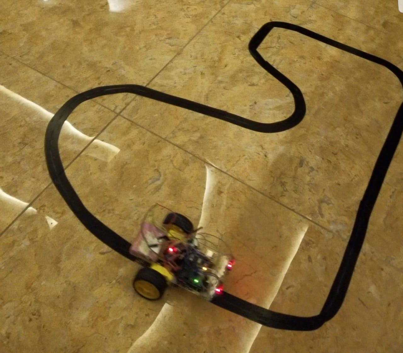
Introduction:
The line follower is a self-operating robot that detects and follows a line that is drawn on the floor. This robot is designed to be able to follow a black line on the ground without getting off the line too much. This line or path may be as simple as a physical white line on the floor or as complex path marking schemes e.g. embedded lines, magnetic markers and laser guide markers. The system used must sense a line and maneuver the robot to stay on course, while constantly correcting the wrong moves.
Basic Components:
- Arduino Uno (1x)
- IR sensors (2x)
- DC Motors (2x)
- L298 Motor driver (1x)
- 12V DC Battery Pack (1x)
- Chassis (robot body including tyres)
- Connecting wires or Jumper wires
IR (Infrared Sensor):
An infrared sensor is an electronic instrument which is used to sense certain characteristics of its surroundings by either emitting and/or detecting infrared radiation. The emitter is simply an IR LED (Light Emitting Diode) and the detector is simply an IR photodiode which is sensitive to IR light of the same wavelength as that emitted by the IR LED. When IR light falls on the photodiode. The resistances and these output voltages, change in proportion to the magnitude of the IR light received.
Motor driver:
The L298N is a dual H-Bridge motor driver which allows speed and direction control of two DC motors at the same time. The module can drive DC motors that have voltages between 5 and 35V, with a peak current up to 2A.
Arduino UNO:
The Arduino UNO is a widely used open-source microcontroller board based on the ATmega328P. The board is equipped with sets of digital and analog input/output (I/O) pins that may be interfaced to various expansion boards (shields) and other circuits. The board features 14 Digital pins and 6 Analog pins. It can be powered by a USB cable or by an external 9 volt battery, though it accepts voltages between 7 and 20 volts
Working:
The robot has two sensors installed underneath the front part of the body, and two DC motors drive wheels moving forward. A circuit inside takes an input signal from two sensors and controls the motor through H-bridge which later controls the wheels’ rotation.
Sense a black line through IR:
For line detection logic, we used two IR Sensors, which consists of IR LED and Photodiode. They are placed in a reflective way i.e. side – by – side so that whenever they come in to proximity of a reflective surface, the light emitted by IR LED will be detected by Photo diode. In case of black surface, which has a low reflectance, the light gets completely absorbed by the black surface and doesn’t reach the photodiode. Then the IR receiver produces output current, depending on the amount of infrared light received. (This current is converted to voltage.)
H-Bridge and Arduino :
We are using two motors for our robot first to ensure that the polarity of the motors is the same on both inputs. Then connect the power supply on the H-Bridge module. 5V h-bridge output is fed to Arduino’s 5V pin to power it. Then we will need six digital output pins on our Arduino, two of which need to be PWM (pulse-width modulation) pins. Finally, connect the Arduino digital output pins to the driver module. The motor direction is controlled by sending a HIGH or LOW signal to the drive for each motor.
Arduino IDE Code:
#define LS 2 // left sensor
#define RS 3 // right sensor
#define LM1 5 // left motor M1a
#define LM2 4 // left motor M2a
#define RM1 7 // right motor M2a
#define RM2 6 // right motor M2b
void setup()
{
pinMode(LS, INPUT);
pinMode(RS, INPUT);
pinMode(LM1, OUTPUT);
pinMode(LM2, OUTPUT);
pinMode(RM1, OUTPUT);
pinMode(RM2, OUTPUT);
}
void loop()
{
if(digitalRead(LS) && digitalRead(RS)) // Move Forward on line
{
digitalWrite(LM1, HIGH);
digitalWrite(LM2, LOW);
digitalWrite(RM1, HIGH);
digitalWrite(RM2, LOW);
}
if(digitalRead(LS) && !(digitalRead(RS))) // turn left by rotationg left motors in forward and right ones in backward direction
{
digitalWrite(LM1, HIGH);
digitalWrite(LM2, LOW);
digitalWrite(RM1, LOW);
digitalWrite(RM2, HIGH);
}
if(!(digitalRead(LS)) && digitalRead(RS)) // Turn right by rotating right motors in forward and left ones in backward direction
{
digitalWrite(LM1, LOW);
digitalWrite(LM2, HIGH);
digitalWrite(RM1, HIGH);
digitalWrite(RM2, LOW);
}
if(!(digitalRead(LS)) && !(digitalRead(RS))) // Finish line, stop both the motors
{
digitalWrite(LM1, LOW);
digitalWrite(LM2, LOW);
digitalWrite(RM1, LOW);
digitalWrite(RM2, LOW);
}
}
Circuit diagram :

Applications of line follower robot:
- Industrial Applications: These robots can be used as automated equipment carriers in industries replacing traditional conveyer belts.
- Automobile applications: These robots can also be used as automatic cars running on roads with embedded magnets.
- Domestic applications: These can also be used at homes for domestic purposes like floor cleaning etc.
- Guidance applications: These can be used in public places like shopping malls, museums etc to provide path guidance.
Conclusion:
In this project, we have designed a line following robot. This robot does not need any controller like Bluetooth, Wi-Fi, GSM, driver etc, it will run automatically with following a line with the help of IR sensors. This robot is very low cost but very effective for various purposes. Our project can be used in various sectors like in medicine delivering in hospitals, delivering products in any places, spying, and surveillance and so on. In future we can add several sensors, cameras etc to get more features.
